


Recently, scientists from the Institute of Solid State Physics, Hefei Institutes of Physical Science (HFIPS) of Chinese Academy of Sciences (CAS) utilized a novel Archimedes spiral flow channel to develop flow-electrode capacitive desalination for seawater desalination.
In recent years, the stack structure of traditional FCDI device suffered serious seeping and streaming problems, strongly impending the industrialization developments of FCDI technology. In traditional FCDI devices, the feed water needs to flow through the graphite plates and ion exchange membranes (IEMs) before entering the water channel. Since the distance between the water channel and flow electrode channel is relatively close, the feed water is easy to penetrate the carbon slurry when it passes through the graphite plates, causing streaming phenomenon. Moreover, due to the large hydraulic pressure in the channels and the stress deformation of spacer, the feed water could seep out from the device, leading to the seeping problem. The suffered serious seeping and streaming problems brings the huge interference to the operational stability of FCDI devices.
Meanwhile, the structure of flow channels is of paramount importance on the flow state of flow electrodes in FCDI devices, which directly determine the desalination performance. Currently, most of FCDI devices adopt traditional serpentine flow channels with many corners. The velocity of flow electrodes at corners is less than that at straight lines, resulting in the poor consistency of desalination performance in whole flow channels. Little attention has been paid to the impact of flow channel structure on the improvement of desalination performance in FCDI devices.
In this work, the structure of FCDI device was improved by changing the direction of saline water for desalination, improving the running stability of FCDI device obviously.
Compared with traditional FCDI device, the feed water directly flows into the spacer in the optimized FCDI device instead of passing the graphite plates to resolve the streaming problems, in which the carbon slurry flow through the flow electrode channels in graphite plates and the feed water traverse to the spacer, respectively.
Meanwhile, the depth of spacer was enlarged by 3 mm to reduce hydraulic pressure and stress deformation for relieving the seeping risk. More importantly, the Archimedes spiral model was introduced to optimize the flow trajectory of carbon slurry for the first time, which vastly boost the desalination performance of FCDI devices. In this case, the computational fluid dynamitic (CFD) simulation was utilized to compare the flow regime of carbon slurry electrode in spiral and serpentine flow channel, showed that more uniform velocity field than serpentine flow channel. Besides, the velocity of carbon slurry in spiral flow channel was slower than serpentine flow channel, implying a longer residence time in spiral flow channel. In desalination test, the average salt removal rate (ASRR) and salt removal efficiency (SRE) of spiral flow channel FCDI device were 0.83 μmol cm-2 min-1 and 13.27% during 1h running period, which are roughly twice as serpentine flow channel FCDI device (0.44 μmol cm-2 min-1 and 8.78%). Both results plenty demonstrated the superiority of spiral flow channel.
For the long-term continuous desalination in 3.5 g L-1 NaCl solution under the batch mode with 5 wt% AC carbon slurry at 2.4 V, the spiral flow channel FCDI device achieved 95.55% of SRE with a superior ASRR of 1.77 μmol cm-2 min-1 and 57% charge efficiency, demonstrating a stable desalination performance.
This work provided a strategy for engineering the flow channels and stack structure to enable high desalination performance, offering guidance for the design of optimizing FCDI device.
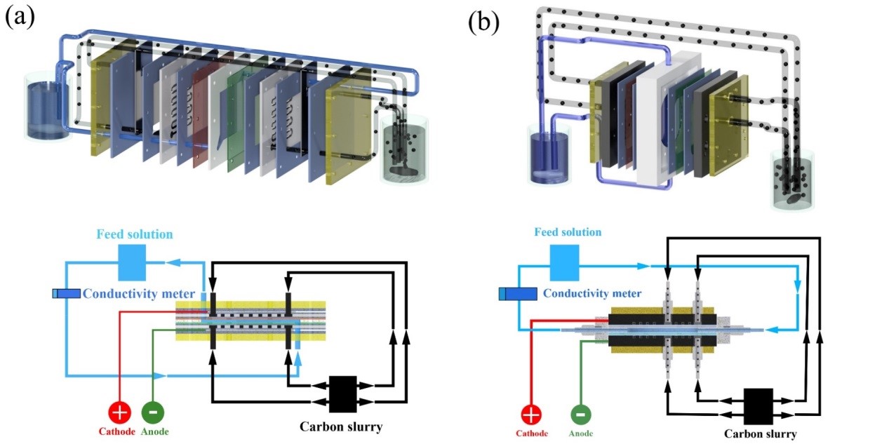
Figure 1. The module structure of (a) traditional FCDI device and (b) optimized FCDI device. (Image by ZHOU Hongjian)
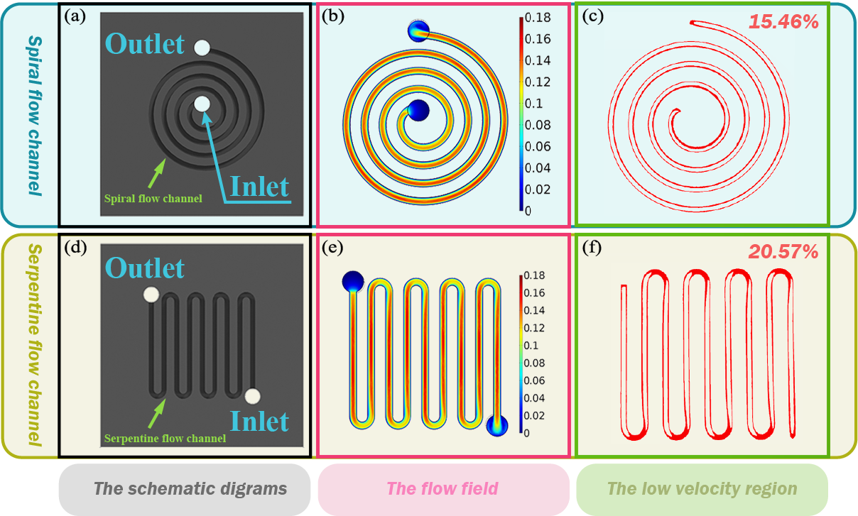
Figure 2. (a) A 2D schematic of spiral flow channel model; (b) Velocity distribution of carbon slurry and (c) low velocity region of carbon slurry in spiral flow channel; (d) 2D schematic of serpentine flow channel model; (e) Velocity distribution of carbon slurry and (f) low velocity region of carbon slurry in serpentine flow channel. (Image by ZHOU Hongjian)